Today in Blakeyrat is always several years behind in every tech trend news...
-
@HardwareGeek ChituBox is the name of it. I think.
The download process is sketchy as hell IIRC. Use a burner email address. But it works well enough.
-
@Polygeekery That's one of the ones mentioned on that web page. I'll give it a try. Thanks.
-
@Polygeekery Didn't seem too terribly sketchy, except that DuckDuckGo Privacy Essentials blocked the Alibaba wannabe-captcha they use, so it took me several tries to figure out what was being blocked, what was blocking it, and disable it so that I could create an account and log in. Also, may or may not be related, something broke Adblock Plus so badly it said it needed to be uninstalled and reinstalled. Also, may or may not be related, something broke that one specific FF window so badly (all the other windows were ok) that I mostly couldn't interact with any of the tabs in that window and had to restart FF. Once I got past the wannabe-captcha on the registration page, though, everything seemed ok.
I've installed it and configured it for the Photon S, but I haven't tried actually slicing anything yet.
In other printing news, LNIL that coffee filters are useless at filtering resin back into the bottles. I thought that even if the resin is too viscous for coffee filters, at least they'd be useful for filtering debris out of the cleaning alcohol. Nope. Maybe they're just clogging to quickly, but the alcohol barely drips through the filter. Maybe I could print something for vacuum-assisted filtration, but the print volume of my printer is so small, I'd have print it in a bazillion pieces and assemble them.
 (The printer came with a few filters, but they're definitely a consumable, and as far as I can find, they don't sell them for the very necessary ongoing use.)
So I looked online and found some reusable wire mesh filters. The vast majority of sellers are in China, with delivery times of 2 weeks to a month. I finally found one in the US with a delivery time of 8 days, so that seller got my business, even if it was a couple of bucks more than the cheapest seller.
-
@HardwareGeek you can use cone paint filters. That's what came with my Photon.
-
@HardwareGeek oh, and as for filtering your solvent, use a layer or two of good quality paper towels. Not the cheap shitty bargain type. The cheap ones clog instantly. Bounty seems to work well, along with Sam's Club and Costco house brands. If you get the "select a size" rolls with the short sections use two layers oriented 90 degrees to each other. It keeps them from falling apart.
I use an old sieve to hold the filter media (paper towel) and filter into an old 4 cup glass measuring cup that the markings are nearly gone from. But anything that will hold the sieve and not dissolve in your solvent should work fine.
-
@Polygeekery said in Today in Blakeyrat is always several years behind in every tech trend news...:
cone paint filters
Ah, that's what those are. Well, I've already bought the infinitely reusable metal mesh filter.
@Polygeekery said in Today in Blakeyrat is always several years behind in every tech trend news...:
use a layer or two of good quality paper towels. Not the cheap shitty bargain type. The cheap ones clog instantly. Bounty seems to work well
Sadly, Bounty has come out with their own shitty bargain towels, and the good quality ones are no longer available, at least not from my usual grocery and household products source.
-
@HardwareGeek said in Today in Blakeyrat is always several years behind in every tech trend news...:
infinitely reusable or until I forget to clean it one time and clog all of the metal mesh filter
-
Any experience with Monocure's resin pigments? Unsurprisingly, their instructions only talk about mixing them with Monocure resin, but I have a large amount of Anycubic resin (and at last check a shipping label for more; I wonder if there is an actual package yet this morning). I figure, worst case, I waste a few drops of pigment, a few ml of resin, and some time.
-
@HardwareGeek said in Today in Blakeyrat is always several years behind in every tech trend news...:
Any experience with Monocure's resin pigments?
Heavy body, almost no head, very harsh, tarry terps.
-
@HardwareGeek I don't see why they wouldn't work with any resin. They should be non-reactive. But using them would change your layer exposure times as they would prevent UV penetration through the resin so keep that in mind.
-
@Polygeekery said in Today in Blakeyrat is always several years behind in every tech trend news...:
They should be non-reactive.
The pigments are suspended in some kind of liquid, and the Formlabs pigments are (or seem to be, based on the info on their website) reactive and can only be mixed with special, compatible resins. I thought perhaps the Monocure pigments were, too, although they can be added to any Monocure resin. I guess I'll find out.
Also, I tried to download the pigment kit MSDS using the link on their site, but got a 404. The error handler page has a discount code, so that may be the happiest I've ever been to not find what I was looking for.
-
As an experiment, I tried printing some articulated, interlocking parts last night. Something similar to this, but a different "weave" and considerably smaller in dimensions. That was ... not a resounding success.
It needed a lot of supports for all the individual pieces. Automatic support generation only created about 2/3 of them; I had to add the rest manually. The slicer was not cooperative about letting me add supports where I wanted to add them. "Computer says no. You can add a support right there, but if you move the pointer 1 pixel in any direction, no support for you." Because of the perspective view, trying to change the viewpoint to see the point where I wanted to add the support was very finicky — move the pointer 5 pixels and the foreground of the view moves 500 pixels. Zooming is similarly tricky; one click of the wheel may zoom the desired point off-screen or behind the camera's clipping plane.
The structure of the pieces was very fine, above the printer's resolution but pushing the limits of its ability to print reliably, especially near the edges of the print volume. Because the structure of the model was so fine, I turned the size of the supports (at least the contact points with the model) as small as they would go, but removing the supports after printing without damaging the model was still hit-or-miss. And there were So. Many. Supports. It took something like an hour of carefully clipping away with flush-cut nippers to get (almost) all the supports removed.
And for all that, overexposure while printing and/or resin residue after printing welded all the individual parts into a single unit. I scaled the model up by 2x after the first attempt (which was so delicate I couldn't even handle it without breaking bits off) in order to get stronger structure and more space between the parts, and it still failed. I think another 2x might get me something printable, except that would then be too big for the printer volume (and bigger than I want the pieces to be). I might also need to make the supports part of the model, itself, rather than relying on the finicky slicer to add them, as I'd then have complete control of where they attach and what direction they run.
-
@HardwareGeek said in Today in Blakeyrat is always several years behind in every tech trend news...:
move the pointer 5 pixels and the foreground of the view moves 500 pixels. Zooming is similarly tricky; one click of the wheel may zoom the desired point off-screen or behind the camera's clipping plane.
Needs a tweak control that takes numeric input, pointer control only is evil.
-
The place I've been buying filament from used to offer refills of ABS, PLA and PETG without spools. So, theoretically, you could buy the filament, print or otherwise obtain an empty spool and stick the thing on there, saving the cost and shipping weight of the spool. However, it looks like they've discontinued selling PLA refills, only offering PETG and ABS in this format. Not only that, but:
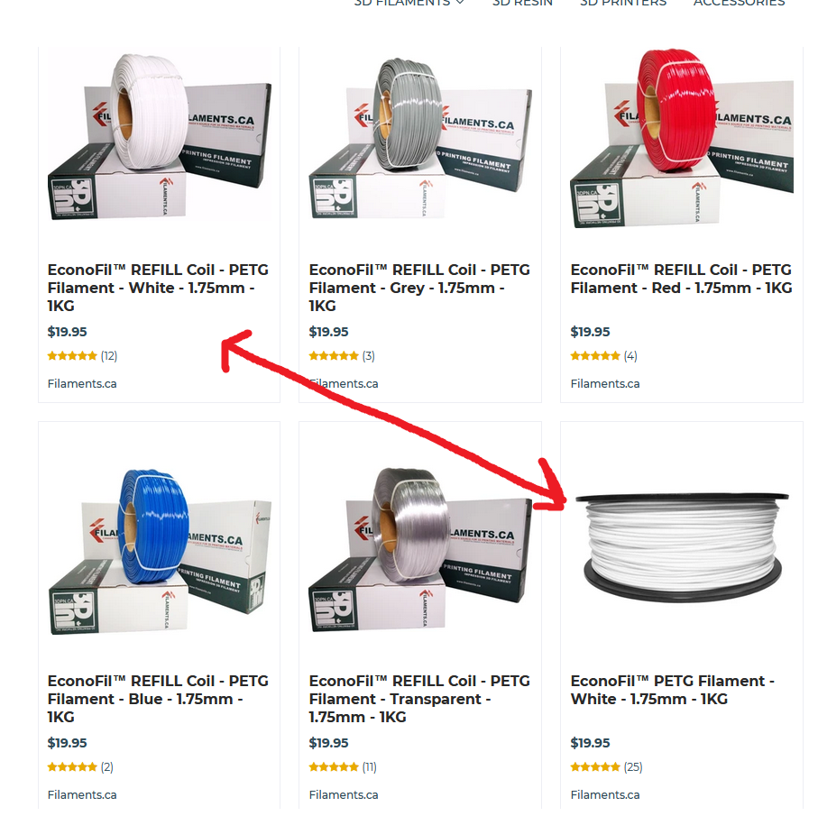
You don't even save any money.
-
@hungrier said in Today in Blakeyrat is always several years behind in every tech trend news...:
The place I've been buying filament from used to offer refills of ABS, PLA and PETG without spools. So, theoretically, you could buy the filament, print or otherwise obtain an empty spool and stick the thing on there, saving the cost and shipping weight of the spool. However, it looks like they've discontinued selling PLA refills, only offering PETG and ABS in this format. Not only that, but:
You don't even save any money.Ouch. And the spooling looks haphazard, at that.
-
I'm experimenting with a new (to me) resin, https://monocure3d.com/collections/rapid-flexible-flex100-resin/products/3d-rapid-flex100-clear?variant=36697892880548, just a few solid and hollow shapes of various sizes, trying to figure out stuff like how flexible it is, how strong it is (i.e., what can I print and how thick to do the walls need to be?), and what settings I need to print it. It really doesn't like to stick to the build surface.
For those of you unfamiliar with resin printing, each layer is exposed to UV light to harden the resin. The length of time it's exposed varies with the printer and resin; with my printer and the manufacturer's own resin, each layer takes 6 seconds by default, and the spreadsheet @Polygeekery mentioned up-thread recommends 22 seconds for my printer and this resin. However, the first few layers typically get exposed longer to help them stick to the build surface better. The default for the printer manufacturer's resin is 60 seconds each for the first 6 layers; I reduced that to 50 seconds, because IME it tends to stick too well most of the time. For this resin, the spreadsheet recommends 80 seconds each for 4 layers. I tried 80; it didn't stick. I tried 120; it didn't stick. I'm now trying 150.
Also, I made a startling discovery this morning. Regardless of which resin you use, it tends to work slightly better if you put the resin in the machine before starting to print.

-
@HardwareGeek said in Today in Blakeyrat is always several years behind in every tech trend news...:
I tried 80; it didn't stick. I tried 120; it didn't stick. I'm now trying 150.
That seems to be making things worse. The only things that printed successfully at 150 were solid cylinders 2, 3 and 4 mm diameter; the 1, 5 and 10 mm cylinders that had printed (somewhat) successfully before failed. One 10 mm sphere (I'm not sure if it was the solid or hollow) didn't fall off, but was so distorted it was hardly recognizable as a sphere. A few of the other supports stayed attached to the build plate although the objects didn't stay attached to their supports, despite using the "heavy" support setting in the slicer. Everything else was bits and pieces in the bottom of the resin vat.
-
Status: Trying to figure out TPU. One of the first things I printed was this temperature tower:
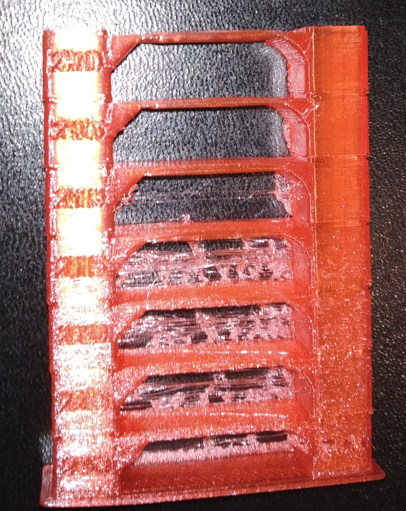
It printed without a hiccup, at all temperatures from 230 down to 200. No jamming or anything Higher temps had bad visual quality and lots of stringing, but both of those gradually got better with lower temperatures, and 200-205 looks perfect. Clear colouration, perfect bridges, no stringing. A++ would print again.
Except I can't get a single thing to print anymore. I've tried starting at 205, 210, 215 and 220, and it can't even get through the first layer before it stops successfully extruding. I haven't tried starting at 230 again like I did with the temp tower, but even if it worked that's not a good solution.
I've considered that maybe it took on a lot of humidity, but it's not like it had much opportunity to do so. After I took it out of the package, I had it out for a few hours while actively printing, then put it back inside a sealed Ziploc bag with a handful of desiccant packets in it.
Were my first couple perfect prints with this material just a fluke? Would I really need to bake the thing before every print to dry it out? Is there something else I'm overlooking?
-
@hungrier Update: Not even 230 works anymore, it just stops extruding. It makes zero sense: I can print PLA and PETG just fine, same as before. I can manually push TPU and even extrude it with the "move axis" menu, and it has no problem at pretty much any temperature above 200. But as soon as I try to print something, even the same file that worked a couple days ago, it prints the priming line, and sometimes lasts long enough to print the first inner wall of the first layer, but can't do anything beyond that.
-
@hungrier I haven't got a printer and so no experience with it, but my first guess would have been that your hotend could have been warmer than the indicated temperatures of the tower. Starting with the lower temperatures might thus not yield the results you'd expect.
As far as I understand the model it starts with the bottom layers on the hottest settings and then has gcode where the hotend is set to a lower temperature. I have read somewhere that hotends are not always very accurate with temperatures and thus might swing around a particular temperature. It's thus possible that its temperature remained slightly higher than indicated when the printer was working its way up the model.
Of course, I have no explanation about why the exact same file couldn't be repeated - it should have identical gcode for the initial heating stage...
What kind of hotend do you have, is it an all-metal one or a PTFE-lined one? Could it be that printing at high temperatures (plus letting it cool down afterwards) warped something? (Though maybe it's better to wait for somebody with real advice before taking apart the hotend...)
-
@hungrier Can you see if the filament is somehow slipping in the extruder? It's a bit of a WAG, but had similar symptoms (extruding in the open fine, printing fails quickly). This was with all materials, though.
For me it turned out the be the extruder, which was wasn't properly gripping the filament. The filament would randomly slip a bit, causing a bit of the filament to be dug away right where it came into contact with the extruder bits. Once that happened, the print failed.
-
@JBert said in Today in Blakeyrat is always several years behind in every tech trend news...:
@hungrier I haven't got a printer and so no experience with it, but my first guess would have been that your hotend could have been warmer than the indicated temperatures of the tower. Starting with the lower temperatures might thus not yield the results you'd expect.
As far as I understand the model it starts with the bottom layers on the hottest settings and then has gcode where the hotend is set to a lower temperature. I have read somewhere that hotends are not always very accurate with temperatures and thus might swing around a particular temperature. It's thus possible that its temperature remained slightly higher than indicated when the printer was working its way up the model.Unless the temp sensor is way off then it should still be close enough, and I more or less babysat the temp tower as it was printing, in case it would jam, and watched each temperature level as it changed. That's also part of the reason I wouldn't consider it acceptable if it worked at 230 on the first layer: To get it back down to 200-205 it would drastically reduce the temp and overshoot it, likely going below 200 before coming back up, which I think would cause even more problems with extrusion.
@JBert said in Today in Blakeyrat is always several years behind in every tech trend news...:
What kind of hotend do you have, is it an all-metal one or a PTFE-lined one? Could it be that printing at high temperatures (plus letting it cool down afterwards) warped something? (Though maybe it's better to wait for somebody with real advice before taking apart the hotend...)
I'm using the stock Ender 3 hotend, with Capricorn tubing. That should theoretically be stable up to 260 (the maximum my hotend supports) and higher. And as I mentioned, I can extrude the same TPU out of it when manually feeding it in or with the menu.
@cvi said in Today in Blakeyrat is always several years behind in every tech trend news...:
@hungrier Can you see if the filament is somehow slipping in the extruder? It's a bit of a WAG, but had similar symptoms (extruding in the open fine, printing fails quickly). This was with all materials, though.
It would be hard to see if it was slipping, but I don't think that's it. I've got a dual gear extruder which as far as I can tell has a very good grip on the filament, and whenever it stops extruding during a print I have to back it off manually and the filament seems to be bunched up somewhere. Maybe the inside of the exit part of the extruder is hollow or something. I don't know where else the filament could go, especially since Capricorn tubing is supposed to have a tighter size tolerance that, among other things, specifically prevents problems like that with flexible filament.
-
Update: TPU is back on the menu boys!
It turns out I was on to something with this:
@hungrier said in Today in Blakeyrat is always several years behind in every tech trend news...:
Maybe the inside of the exit part of the extruder is hollow or something.
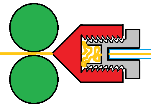
That part of the extruder isn't quite hollow, but does have a lot of empty space just waiting for a strand of flexible filament to get slightly kinked and go off the straight path, which then creates a big spaghetti mess. I've made this highly technical and microscopic scale accurate diagram to demonstrate:
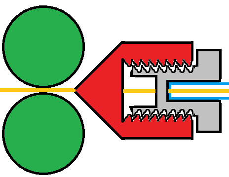
The dual extruder gears (green) push along filament (yellow) into the back of the extruder (red) which has a bowden connector (gray) threaded in, and PTFE tube (blue outline) coming out. There's a big empty space between the inside wall of the extruder and the end of the bowden connector, and it's one of the ones that blocks the PTFE tube from going all the way through. PLA, PETG etc are rigid enough that they can go straight through without any problem, but flexibles can bend in that small area, and have plenty of space for something like this to happen:
I happened to have a bowden connector that does let the tube go through, so I swapped it and now I have a situation that looks like this:
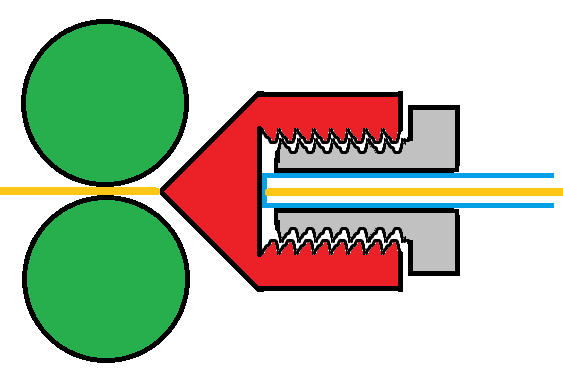
Which so far has been working


-
@hungrier said in Today in Blakeyrat is always several years behind in every tech trend news...:
That part of the extruder isn't quite hollow, but does have a lot of empty space just waiting for a strand of flexible filament to get slightly kinked and go off the straight path, which then creates a big spaghetti mess.
Yep. TPU and other flexibles are a total PITA with a Bowden setup. I'm not saying that it cannot be done. You showed that it could be done. But it is a pain and source of frustration.
If you want to do flexibles I would strongly encourage moving to a direct drive setup. I have had zero TPU printing issues since moving to a BMG direct drive extruder. If you solve the filament path problem on a Bowden unit you still have to deal with the distance between melt zone and extruder. Since flexibles are flexible they stretch and it takes more retraction to prevent seepage, but you can only retract so far before you start jamming. Too much retraction allows the melted bit to solidify and your melt zone is slightly larger in diameter than the filament pathway.
Now, you can accommodate for this, somewhat, in some models. If your model builds up in such a way that you do not end up building multiple separate "towers" (not sure what to technically refer to them as) then you can set your slicer to never cross perimeters and any stringing will be confined to infill. Prusaslicer for example:

Turn on the "Avoid crossing perimeters" and set the max detour length to something larger than your print bed diagonal and it will make absolutely certain that it never ventures outside of the model as it builds up the layers. You still have stringing, but you won't ever see it as it is hidden inside the model. If your model requires you to cross empty areas in the slice then the stringing is unavoidable (for all intensive porpoises).
-
@Polygeekery I'm still considering a direct drive conversion as a possible future upgrade, especially if I want to get into any of the even softer flexibles. Or maybe even go down the path of buying another printer for flexibles - I recall hearing about some cheap one that's got direct drive stock and is garbage in general but apparently really good for very soft materials. I think it was a CHEP video demonstrating it.
Anyway, when I was preparing to get into flexibles I discovered a severely underrated and under-subscribed channel with 3D printing info: Lost In Tech.
https://www.youtube.com/watch?v=lD9Ei3u5-iU
The video blew my mind, because everyone else had pretty much said, forget about retractions if you're doing TPU on a bowden setup. This guy gave some tips and actual demonstration that if you have enough patience to dial it in, you can get great results. He has some other interesting things on his channel, including a fancy (although complex and time-consuming) first layer test pattern and some plate adhesion torture tests.
-
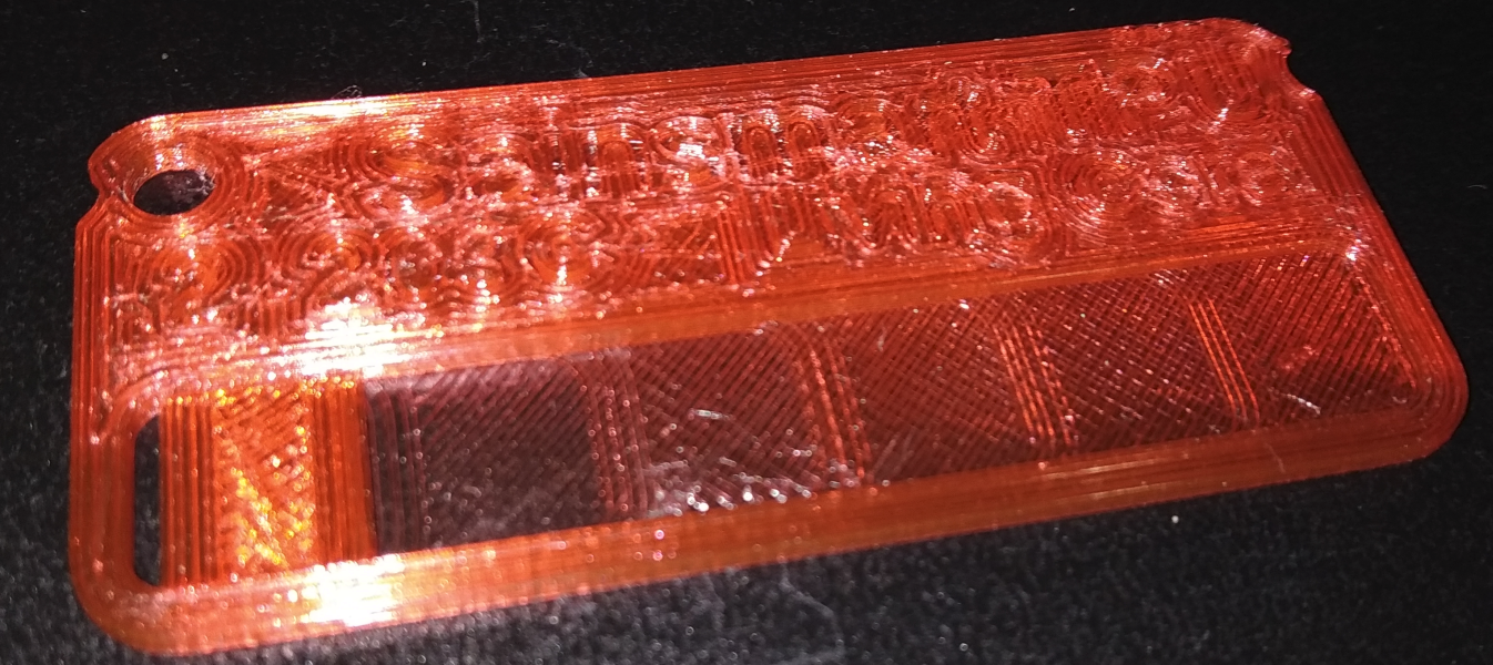
Was printing a few different parts today (first time in a while). Ended up loading an old spool of TPU filament after being reminded of it in this thread. Hadn't used it much. Let's see if works out. Part isn't very complicated, so I'm not expecting too much trouble. *knocks on wood*
-
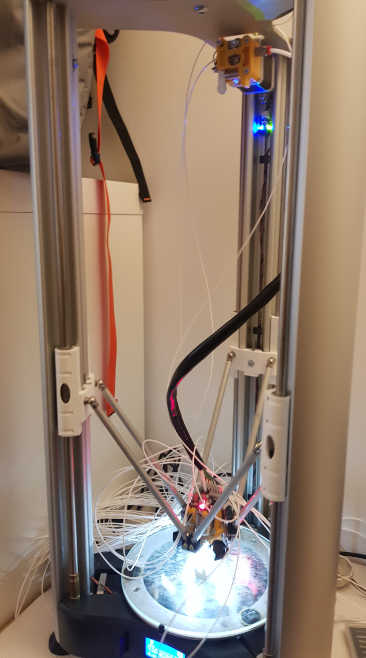
ERROR_SUCCESS, I think. Filament spool decided to continue unspooling itself (by itself) somewhere along the print, spilling filament all over the place. Some visible in the picture below, rest is on the floor below. Printer and print didn't mind too much (a bit of luck with the filament not getting in the way or getting caught on anything). Print finished not much after I finished respooling the filament.
-
@cvi you can also name the photo "unexpected visitor in the teleporter"
-
Status: Oops, I accidentally clicked the "Last Post" throbber and lost my place in the thread.
Sorry in advance for all those who were looking forward to their upvotes...
-
What CAD software do y'all use for 3D printing?
I've been using Blender because I have it and am throughly familiar with using it. It can import and export .stl files, and it can create objects with dimensions far more precise than any 3D printer (if you set the basic unit to mm, it will display dimensions to 0.1 µm), but it doesn't really make that kind of design easy. (INB4 "Blender doesn't make anything easy." Shaddup; I've been using it for a couple of decades, and I know what I'm doing.) So I'm looking at using more of a real CAD program.
The model railroad CAD program I mentioned in another thread will probably do the job, too, but it's really optimized for laying out track and landscape. It can do more general CAD, but it's not really designed for it.
And a bit OT, do any of you have experience with small-run circuit board manufacturing? I found a company that can make boards for $3 apiece for as few as 3 boards (I'm looking at maybe 25), which is pretty good, but with very strict limitations (Cheaper: We'll make it with whatever material, thickness, color, etc. we bought cheap. Not quite as cheap: We'll make it with exactly this material, no options.), and what I want is smaller than their minimum board width. Any of these companies that will assemble the boards, too? And if you have such experience, what software do you use to design the circuit boards?
-
@HardwareGeek I've been using OpenSCAD for most of the stuff I've designed myself. It's code based rather than visual, and you program the model with primitives and operations to manipulate them. Coming from a programming background I find it very intuitive, and so far I've been reasonably satisfied with the tools it comes with, but there are also libraries available for e.g. rounding things, generating threads and gears, etc.
It also supports importing and working with STL files, but I've found that sometimes if the geometry is too complex or the model isn't perfect, the preview will work but the actual renderer will crap out and you won't be able to generate an STL from it.
-
@HardwareGeek said in Today in Blakeyrat is always several years behind in every tech trend news...:
And a bit OT, do any of you have experience with small-run circuit board manufacturing?
I used https://jlcpcb.com/ for a 5 pieces run, only boards withhout assembly and was satisfied. (edit: they do less than 5 units)
Mind, I'm not a pro. Currently finishing three more designs to order.
Currently they have a promotion https://support.jlcpcb.com/article/146-2-for-1-4-layer-pcbs
$2 for 1-4 Layer PCBs
SPECIAL OFFER
$2 for 1-4 Layer PCBs, with free SMT assembly
For 1-4 Layer PCBs with 1oz. Cu, HASL surface finish, you can get below special offers.Layer PCB Size Qty Price
1-2 Layer 100x100mm 5pcs $2
4 Layer 50x50mm 5 pcs $2pcb capabilties at https://jlcpcb.com/capabilities/Capabilities
I found a company that can make boards for $3 apiece for as few as 3 boards (I'm looking at maybe 25), which is pretty good, but with very strict limitations (Cheaper: We'll make it with whatever material, thickness, color, etc. we bought cheap. Not quite as cheap: We'll make it with exactly this material, no options.),
You can do a quote to see if it lets to select the variants you want
and what I want is smaller than their minimum board width.
I can't quote the minum dimensions, but if your design goes under minimum then you can order panelized with v-cuts / v-scoring (https://www.multi-circuit-boards.eu/en/pcb-design-aid/mechanics/v-scoring.html)
Any of these companies that will assemble the boards, too? And if you have such experience, what software do you use to design the circuit boards?
Yes, it does assembly but it only handles around 40000 components. I have the vague impression that Seed ( https://www.seeedstudio.com/fusion_pcb.html ) bragged about how much components can source, but I never worked with them.
If you end ordering only pcb and your design is SMD then remember to order stencil(s)
-
@cabrito said in Today in Blakeyrat is always several years behind in every tech trend news...:
you can order panelized with v-cuts / v-scoring
Perfect. That's explicitly not allowed by the company I was looking at.
Yes, it does assembly but it only handles around 40000 components.
No problem. I'm looking at something like 5 LEDs, a regulator, and a couple of capacitors and resistors. Trivial, except the regulator I was looking at is only available in a surface-mount package, which can be a little tricky to solder if you don't know what you're doing. (I have no first-hand experience with surface-mount, which is why I was looking at a few extra boards for spoilage.)
-
@HardwareGeek said in Today in Blakeyrat is always several years behind in every tech trend news...:
And a bit OT, do any of you have experience with small-run circuit board manufacturing?

@HardwareGeek said in Today in Blakeyrat is always several years behind in every tech trend news...:
I found a company that can make boards for $3 apiece for as few as 3 boards (I'm looking at maybe 25), which is pretty good, but with very strict limitations (Cheaper: We'll make it with whatever material, thickness, color, etc. we bought cheap. Not quite as cheap: We'll make it with exactly this material, no options.), and what I want is smaller than their minimum board width.
If your boards are that small, the best option is a panel, i.e. multiple copies of the same board next to each other:
PCB PANEL DESIGN
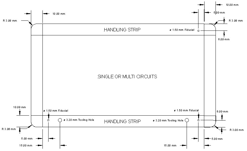
Once the PCB design has been finalized the next phase is to send the PCB data away to a PCB manufacturing company along with a panel design specification to ensure that the format the PCB's are received is as expected.
You can generate the panel files from the single board files yourself, but it's usually easier and less error-prone to let the PCB manufacturer do it if they offer the option.
@HardwareGeek said in Today in Blakeyrat is always several years behind in every tech trend news...:
Any of these companies that will assemble the boards, too?
Some of the PCB manufacturers do offer assembly services as well, yeah. Here's a useful site:
A Price Comparison Site for Printed Circuit Boards

PCBShopper is a price comparison site for printed circuit boards. Enter your PCB's specs and immediately see prices from more than 20 PCB manufacturers.
I can't offer much first-hand advice, since the companies I usually rely on for manufacturing and assembly are in Europe and focus more on "high quality" than "lowest price". But I've heard mostly good feedback about companies like PCBway, JLCPCB, OSHpark, etc. for hobby use (as long as you don't mind sending your production files going to
 ).
).@HardwareGeek said in Today in Blakeyrat is always several years behind in every tech trend news...:
And if you have such experience, what software do you use to design the circuit boards?
Altium Designer. But it costs waaayyy too much for hobby use.
For non-commercial/open-source use (don't remember the exact license terms), there's a free version called CircuitMaker.There are plenty of different PCB design tools, but if you want something that's both open-source and good enough in most cases, I'd recommend KiCad.
(
 ed by @cabrito)
-
@HardwareGeek said in Today in Blakeyrat is always several years behind in every tech trend news...:
the regulator I was looking at is only available in a surface-mount package
And it's not one that JLCPCB stocks. :( I'm sure something similar must be available among the LED drivers/regulators they do stock.
@Zerosquare said in Today in Blakeyrat is always several years behind in every tech trend news...:
there's a free version called CircuitMaker.
I was looking at that yesterday. I still have the tab open (of course, one of the hundreds I still have open).
I'd recommend KiCad.
I'll take a look at that, too. (Yeah, another tab!)
-
@HardwareGeek said in Today in Blakeyrat is always several years behind in every tech trend news...:
@cabrito said in Today in Blakeyrat is always several years behind in every tech trend news...:
you can order panelized with v-cuts / v-scoring
Perfect. That's explicitly not allowed by the company I was looking at.
Yes, it does assembly but it only handles around 40000 components.
No problem. I'm looking at something like 5 LEDs, a regulator, and a couple of capacitors and resistors. Trivial, except the regulator I was looking at is only available in a surface-mount package, which can be a little tricky to solder if you don't know what you're doing. (I have no first-hand experience with surface-mount, which is why I was looking at a few extra boards for spoilage.)
Good, you can order to assembly only the SMTs. They also asse mbly through-hole, but don't if they handle mixed assembly.
And if you have such experience, what software do you use to design the circuit boards?
At the time (one year ago) i tried many free EDA soft, and setled with Kickad
Has a lot of small anoyances but I choosed as the least infuriating. Files are pure text, easy to parse to do things like standarizing drill diameters in a few buckets.
Don't use ExpressPCB, it has some great qualities but it cannot export to gerber, the universal format accepted in all fabs
-
@HardwareGeek said in Today in Blakeyrat is always several years behind in every tech trend news...:
And it's not one that JLCPCB stocks.
How small is it? If it's something like SOIC for example, soldering it yourself with a standard soldering iron is definitely doable, even if you're not experienced.
-
@HardwareGeek So far, I've also used Blender. Mainly for the same reason as you mentioned. Though in my case, it's more of passing familiarity. I've never been great at modeling. Creating some simple functional (but not very pretty) parts or modifying existing stuff works, though.
Tried Autodesk's Fusion360 (I think that's the freemium thing they offer). I can see why one might want to use it over e.g. Blender. Personally wasn't that fond of it. Ran like ass on my machine too.
Installed OpenSCAD, but never got around to playing much with it. @hungrier's description makes it sound like I should give it another shot.
-
@Zerosquare said in Today in Blakeyrat is always several years behind in every tech trend news...:
There are plenty of different PCB design tools, but if you want something that's both open-source and good enough in most cases, I'd recommend KiCad.
Spent a few days messing around in KiCad not too long ago. Should pick that project up again. (Have the slight feeling that it'll take a bit more than a few days to get anywhere useful, though.)
-
@Zerosquare said in Today in Blakeyrat is always several years behind in every tech trend news...:
@HardwareGeek said in Today in Blakeyrat is always several years behind in every tech trend news...:
And it's not one that JLCPCB stocks.
How small is it? If it's something like SOIC for example, soldering it yourself with a standard soldering iron is definitely doable, even if you're not experienced.
TQFN. 16 whatever they're called; I almost said 16-pin, but they're not pins.
-
@HardwareGeek said in Today in Blakeyrat is always several years behind in every tech trend news...:
TQFN. 16
That one is definitely difficult to solder if you don't have a hot air station and experience using it. So indeed, better use something else if the board assembly house can't do it for you.
-
By the way, when you say "5 LEDs", do you mean the "indicator" kind, or the "lighting" kind? If it's the latter, thermal management is important if you don't want to end up with something that overheats. A cheapo PCB is a Bad Idea here (commercial LED lightbulbs typically use special metal-core PCBs for better thermal conductivity, but most cheap PCB manufacturers won't offer that).
-
@Zerosquare said in Today in Blakeyrat is always several years behind in every tech trend news...:
That one is definitely difficult to solder if you don't have a hot air station and experience using it.
Meh. They're nearly impossible to desolder without hotair but soldering them isn't too bad if you have electronics tweezers and hands that aren't too shaky. Tin a pad, spread some flux on the area and then reflow the solder on that pad as you place the device. Then tack a pad on the other side and from there you can solder the rest.
Oh, wait, I just looked that package up to make sure I was thinking of the correct one. Those little bastards are 3mm square. Fuck that. Let the board manufacturer do that or pick another part.
-
@Zerosquare said in Today in Blakeyrat is always several years behind in every tech trend news...:
By the way, when you say "5 LEDs", do you mean the "indicator" kind, or the "lighting" kind?
Both, sorta. Interior building lights for the model railroad industrial building I mentioned in the analog hobbies thread, but really pretty dim, lighting a tiny space no brighter than the normal room lighting that will pass for "exterior daylight" for viewing the layout as a whole. I wouldn't really expect the lighting to be noticeable except during room lights-off "nighttime". So lighting, but dimmer than most indicator LEDs (especially those *%$&@#(%&* super-bright blue LEDs that board designers seem to get off on these days). I was looking at some 3mm through-hole LEDs rated at 20mA and thinking something like 5mA might give me about the brightness I want, but if I have to go SMD for the regulators, I might as well go for SMD LEDs, too. Still probably 5mA for a 20mA LED. (A single LED would probably be more than bright enough to light the entire building, but it wouldn't look right, because a real building would have multiple light sources, so I'd rather have a bunch of dim LEDs than one bright one. If I wanted one LED, I'd just solder an LED to a current-limiting resistor, put some shrink tubing around it, and call it a day, rather than trying to figure out circuit boards I can hide in the roof beams.)
Or ... I just had another idea. I could use a single LED and a light pipe or pipes to distribute it around the building.
-
Oh, OK. No need to worry about heat, then ; any old piece of PCB will do.
-
FYI, if you decide to go the regulator route, you don't need fancy stuff to drive 5 mA into a bunch of LEDs. Something like this is enough:
https://www.digikey.com/en/products/detail/texas-instruments/LM334Z-LFT1/3640537
Pretty common and cheap, only requires one resistor, easy to solder.(maybe the discussion should be Jeffed here? We've drifted pretty far from 3D printing.)
-
TIL don't trust a Thingiverse model to print correctly out of the box. Besides my perennial size problem (most models are designed to be printed on filament printers that can print much larger objects than my resin printer — 200 mm x 200 mm x 250 mm for an Ender 3 vs. 65 mm x 115 mm x 165 mm for my Photon S), which necessitates cutting many models into multiple pieces and assembling them after printing, there's a matter of the author creating the model properly.
The slicer (at least the two that I've used) treats an STL file as a single, indivisible object, even if it's made up of multiple unconnected parts; the individual parts cannot be manipulated individually. And the slicer, by default, places the object so that it's lowest point is touching the build surface. That's fine, if the bottoms of all the individual parts are at the same Z coordinate; not so great if they're not.
The house I'm printing for my (hypothetical, someday) model railroad town is made up of many individual parts, much like if you bought an injection molded polystyrene model kit from your local hobby shop (except the parts aren't connected by sprues and runners, and there are no assembly instructions — that I've found yet, anyway). In particular, there are sections of porch railing that are grouped into a single STL file (that creates a single object when it's imported into Blender, which in turn creates a single STL file when it's exported again — I had to do that, because as the pieces were originally laid out, they were too big in X and/or Y for my printer). This file failed to print correctly twice, failing in the same way both times.
After the second failure, I suspected the cause, so I checked the part in Blender, and I was right. One section and one end of another section were floating slightly above the Z=0 plane. They didn't print correctly because they were never attached to the build surface at all (or only insecurely along a single edge). 3D printers really don't like printing things hovering in midair.
(Come to think of it, it's possible I was too hasty in assigning blame to the author. It's possible I introduced the error when I was manipulating the objects to make it fit my printer, but a couple of other railing sections were upside down, so I doubt it. But I'd have to extract the original STL from the .zip again to be sure, and
.)
-
@HardwareGeek said in Today in Blakeyrat is always several years behind in every tech trend news...:
If I wanted one LED, I'd just solder an LED to a current-limiting resistor, put some shrink tubing around it, and call it a day, rather than trying to figure out circuit boards I can hide in the roof beams.)
Or ... I just had another idea. I could use a single LED and a light pipe or pipes to distribute it around the building.That all seems like way more work than necessary for driving LEDs at low lighting levels. Stick with the current limiting resistor idea What's your power source going to be? If you will have 12V or more available then you could look at running your LEDs in series and only have to worry about one resistor per series run. If you're looking at ~5ma, and the sources I found by Googling and clicking on the first result that doesn't look fucking retarded shows a forward voltage of 3.2-3.8V for warm white LEDs. So you could run three LEDs on each series resistor at 12V supply voltage with a voltage drop across the resistor of 0.6-2.4V. At worst case scenario your load resistor would only be dissipating 12mw of heat.
You would also be looking at 120mw of total power consumption for those LEDs so no need to ever shut them off. Just leave them on forever. Underdriving them that much would make them last effectively forever (considering how goddamn old you are, they would likely outlive you
 ) and you'd be looking at 8,333.3 hours before paying for your first kilowatt-hour. Almost one kilowatt-hour per year. Unless the world goes further to shit then chances are you drop more money in a year and don't bother picking it up than that would cost you.
Someone can feel free to check my math on all of that. It was all done in my head at the end of a long day. Chances of forgetting to carry zeroes approaches unity.
-
@Zerosquare said in Today in Blakeyrat is always several years behind in every tech trend news...:
Something like this is enough:
Yeah. The reason I was looking at the other one is that it can drive up to 5 LEDs in parallel with identical current through each, based on a single resistor for all 5. That mattered more when I thought I was going to be using many LEDs. If I go the light pipe/fiberoptic route, using a single LED for the whole building (or two, one for the factory floor and one for the office area), then the whole regulator thing becomes almost overkill; a central regulated voltage supply and single current-limiting resistor per LED is adequate.
(maybe the discussion should be Jeffed here? We've drifted pretty far from 3D printing.)
Yeah, probably, if we were going to continue this subthread. But I think that question has been adequately answered at this point.
-
@HardwareGeek said in Today in Blakeyrat is always several years behind in every tech trend news...:
The slicer (at least the two that I've used) treats an STL file as a single, indivisible object, even if it's made up of multiple unconnected parts; the individual parts cannot be manipulated individually.
I know you're not doing FDM but download Prusaslicer. There's a ton of ways to split a STL made of multiple distinct bodies but Prusaslicer probably makes it the easiest.
Also, regarding other gripes with slicers, the big names in FDM slicers (Cura and Prusaslicer) will allow you to sink a model below the buildplate and/or stop slicing/printing at specific heights and all sorts of other useful things so you don't have to open up Blender or Meshmixer or whatever to manipulate the model in simple ways. Which, since I suck at all of that I end up with non-manifold models that cause the slicer to shit itself.
A while back I needed to print a part for an electronics enclosure that had printed standoffs to hold controller boards (dumb idea in most cases) on one side and pointing up the other direction were mounting tabs. So no way to print it as-is without a metric shitton of support material.
My solution was to flip the side with the printed standoffs, that would almost certainly break off, down and drop the plane they protruded from to the buildplate, making them unprintable and what remained printed without supports. Then when it was done I drilled out the holes where the printed supports should have been and used them to hold brass standoffs.
If that doesn't make sense I can illustrate it with screenshots tomorrow and it will. The concept is extremely simple for something that requires so many words to explain.
FDM slicers have a hell of a lot more creature comforts and better workflow than their DLP/SLA/Resin counterparts.
 https://www.amazon.com/dp/B0896YBK44/ref=cm_sw_r_cp_apa_glt_fabc_4HNS6WCB3DN3B4MSRGCN?_encoding=UTF8&psc=1