The Official Electronics Projects Thread
-
Thought I'd quit polluting the Status Thread with these and put them in their own place. And I'm sure some of you guys have some interesting custom electronics projects to share, too.
I've been tinkering with my own design of guitar overdrive pedal (the thingy that takes a "clean" electric guitar signal and makes it "distorted" or "fuzzy"). I'm not doing anything revolutionary here, the design is 95% just an Ibanez Tubescreamer with minor alterations and I started with this very-good circuit analysis: https://www.electrosmash.com/tube-screamer-analysis
But I got into PCB design as a result of this. It's been a fun learning project. For schematics and layout, I use https://easyeda.com/ and they have the option to send a PCB to Shenzhen for production. I'm sure Shenzhen has teams of engineers looking at every design that comes through their factory, to reverse-engineer them and rip them off, but they're very cheap and since this is just another Tubescreamer clone in a world that already has hundreds of Tubescreamer clones, I'm not worried.
I just finished designing the fourth revision of my board. Here's a bit of history, and to show my learning process.
Revision 1:
First-ever PCB that I designed and ordered. It worked just fine, but I made a rookie mistake and the board was physically too large to fit in the enclosure.
 I don't have any images or remaining parts on this one. It was a sparse board, with lots of empty space.
Revision 2:
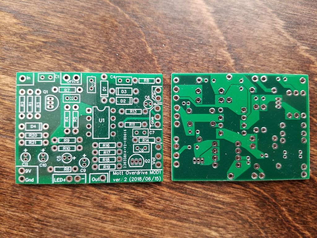
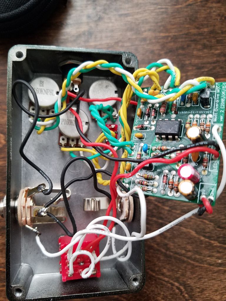
This one fits inside the enclosure, and all my working prototypes use this board. It has problems, though. The board floats inside the chassis, and even with layers of conformal coating and electrical tape, it still likes to short out when everything's buttoned up just because the board's still large and there's physical pressure trying to screw the enclosure's bottom on. I also found a layout error with the tone control (one leg of the tone pot goes to the wrong pin on the op amp). The tone control seems to work just fine though. Lastly, assembly's complicated because none of the switching/bypass stuff is on the board, and the LED circuit is handwired and not on the board. I have to cut and place a lot of wiring and it takes significant time.
Revision 3:
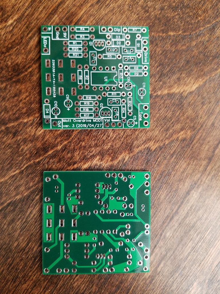
I managed to shrink this one further, but the biggest development was adding holes that line up with the TPDT switch. This moved all the switching to the board, as well as the LED control, and eliminated a ton of hand-wiring during assembly. The switch also physically supports the board and holds it in place. Unfortunately, this one does not work. It makes sound but there is no distortion at all. There must be a layout error in the op amp feedback circuit (that's where clipping occurs) but I poured over the board file for a few hours and could not locate anything wrong. I built three of these and they all had the same problem.

Revision 4:
Still waiting to receive them. I started from scratch again, hoping that I wouldn't make the same mistake as on the Rev 3 board. I also made the bold decision to switch to SMT parts to make everything even more compact.

Prototype Power Supply:
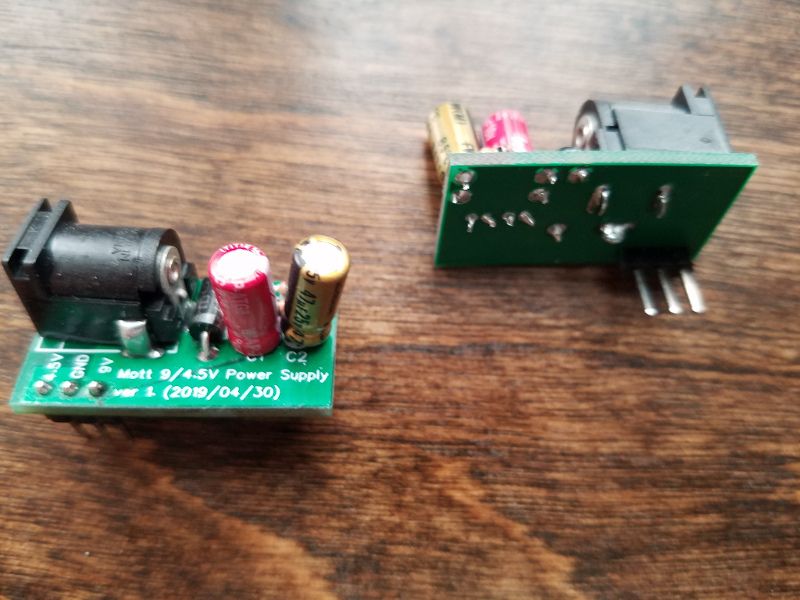
One of the things that annoyed me during breadboarding is I always had to wire up a power supply and some unity gain buffers. So I designed some little boards that I can just pop onto the breadboard and save me some time. Here are pictures of the power supply, which take 9V in and give you 9V and 4.5V which are needed on pretty much any instrument pedal design. I also made a unity-gain buffer but I guess I never assembled any because I can't find them.
Now you professional electronics engineers can start telling me how dumb I am, because I am completely self-taught at electronics.

-
Here are some oscilloscope images of what it does. Sorry for the quality but I literally have the world's cheapest o-scope (I think it was around $25...)
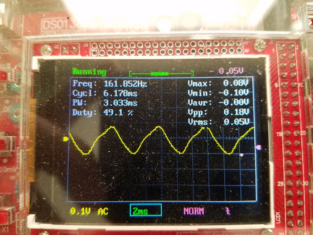
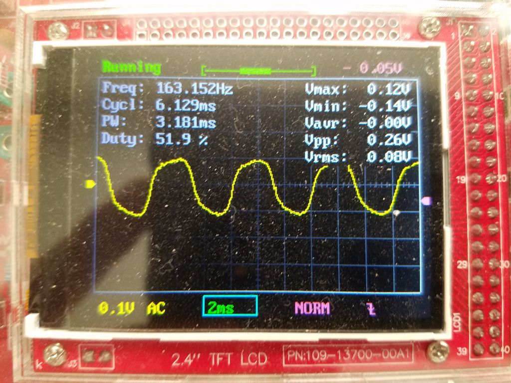
This is an E3 note played on the neck pickup with the tone control rolled all the way down. I'd never play a guitar like that, but it gives you a very clean almost-sinusoidal signal with almost no harmonics so it's easy to see what's going on. The first image is the unmodified clean/bypass signal. The second is the distorted signal with the gain/distortion control maxed out. You can see the distorted signal is much more rounded and has a bit of high-frequency content superimposed on it.
Clean:
Distorted:
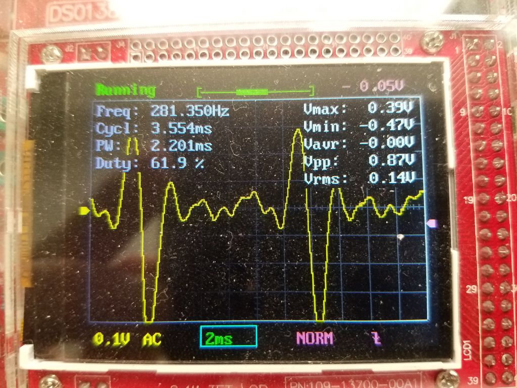
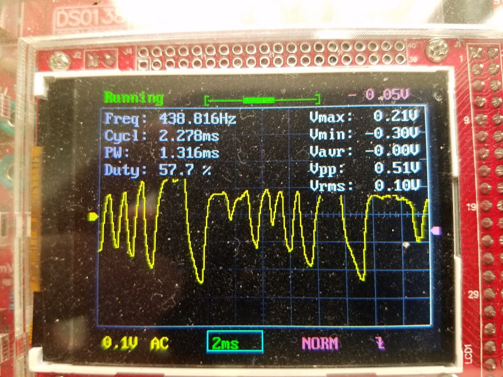
And here's a more typical case. E2 note on the bridge pickup at full tone. Lots of harmonics but it'll still sound clean. The second image shows the distorted signal, and you can see it's highly compressed. The peaks are squashed, the low parts are amplified, and everything's rounded off. This is what makes a guitar sound "distorted," a.k.a. the loud, fuzzy heavy metal sound, compared to a clean tone you'd hear in a lot of country or in stuff like the Beach Boys.
Clean:
Distorted:
-
@mott555 where did the rest of this thread go? I see only two posts now.
Edit: ok, got it, NodeBB upgrade. Nothing to see here, please move on...
-
@robo2 It confused me too because I returned here to report on my latest PCB. It initially didn't work because the footprint for the two voltage-follower BJT's was wrong, it had the base and emitter swapped. I removed the BJT's and awkwardly soldered them down backwards, and now the device passes sound. Don't trust EasyEDA's footprints!
However, it has no distortion. Same exact problem as the previous PCB. I think I need to revisit some things with a breadboard because this isn't a layout problem (not on two independent PCB's of radically different design). I have picked up a schematic flaw or a fundamental misunderstanding regarding the clipping circuit in the opamp, that didn't exist in the earlier PCB's that worked.