Let's see who else will solve this...
-
So, today one of my former pupils wrote to me that he had stumbled across a circuit schematic and wasn't quite able to find out what it's for. But surely I, the residential circuit genius (well, the bar is pretty low to be fair) would be able to identify it?
And I did. But I'd like to see if someone else here will manage that as well? If you do solve it hide your solution via details please. Clicking on the picture will yield a sharper image, mind ;)
-
Google says
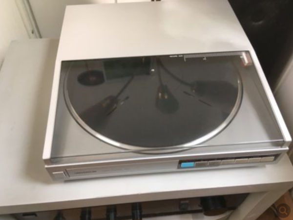
It's a record player.
Edit: Yes, cues:
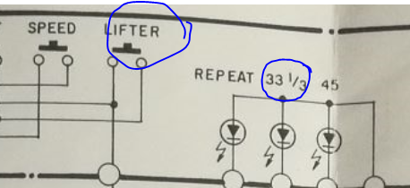
Multiple speeds, automatic repeat, this one's fancy, huh?
-
-
Well, given that it says 33 and 45 along the top, I'ma have to guess it's a record player/gramophone's something-or-other?Also, I can never remember the damnable syntax to make the summary part work right...
-
@e4tmyl33t said in Let's see who else will solve this...:
Also, I can never remember the damnable syntax to make the summary part work right...
It's just another HTML tag right inside the details tag.
-
@tsaukpaetra I tried that but it didn't seem to work...
Test
Oh. It needs to be FIRST. Ok, that would explain it.
-
I'm going to go with "record player", simply because it has start, stop, motor, lifter etc. written on it.
-
I'm thinking it's a two-turntable setup.
-
I think it's a cassette player
-
It's a very complicated method of electrocuting anyone who touches it
-
Record player, I'm pretty sure. (The block at the top with the sizes is a bit of a giveaway.)
-
@rhywden Not yet having looked at any of the previous details...
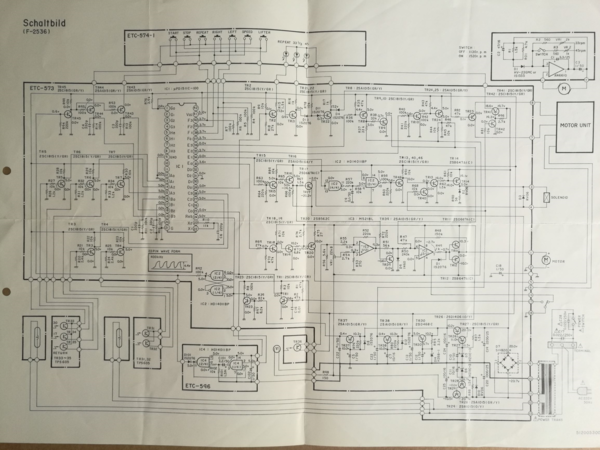
The 33 1/3 and 45 are a dead giveaway that it's from a phonograph. It appears to be just the turntable and arm motor control; there's no sign of connections for the pick up nor speakers, so it doesn't include the audio amplifier.The power supply is obviously at the lower right — transformer, full-wave bridge rectifier, filter capacitors, voltage regulation with zener diodes and pass transistors. The NAND gates bottom center appear to generate a power-on reset pulse for IC1, whatever it is.
I assume IC1 does some sort of event sequencing in response to the control pushbuttons at the top, but exactly what it does is a mystery. Google fails to return any relevant results for the part number. (Amusingly, the top result is for Amazon, a "Real Feel Deluxe No 1 Wallbanger Vibrating Dildo Waterproof Flesh 6.5 Inch". I'm pretty certain that's not what this circuit diagram is for, if for no other reason than all the ancient discreet transistors wouldn't fit.)
I'm going to guess the lamps and optical detectors at the bottom left detect the size of the record on the turntable and maybe the position of the arm. The transistors to the left of IC1 amplify the signals from the optical detectors and send them to the sequencer. The transistors to the right of IC1 are mostly controlling voltages to the various motors; I admit I haven't looked at them in any detail. There are a few other things going on, like driving the front panel LEDs, but that's basically it.
-
@tsaukpaetra said in Let's see who else will solve this...:
Google says
It's a record player.
Edit: Yes, cues:
Multiple speeds, automatic repeat, this one's fancy, huh?Don't believe everything Google says. It also says the chip in the middle of the diagram is a "Real Feel Deluxe No 1 Wallbanger Vibrating Dildo Waterproof Flesh 6.5 Inch".
-
@hardwaregeek
"Always 'Wallbanger'?""_Especially_ 'Wallbanger'"
-
@hardwaregeek said in Let's see who else will solve this...:
@tsaukpaetra said in Let's see who else will solve this...:
Google says
It's a record player.
Edit: Yes, cues:
Multiple speeds, automatic repeat, this one's fancy, huh?Don't believe everything Google says. It also says the chip in the middle of the diagram is a "Real Feel Deluxe No 1 Wallbanger Vibrating Dildo Waterproof Flesh 6.5 Inch".
Okay, okay, intelligently-queried Google says...
Actually, the next best thing was apparently a pair of shoes...
-
I’ll add my voice to the chorus that it’s a record player, based on the “45" and “33 1/3” at the top, and I can’t think of much else that operates at both those values. It does seem to have a bunch of automatic functions that aren’t on a simple player, though.
-
Ok, just from a very cursory glance:
Seems there's some kind of frequency regulation of motors happening here, no MOSFETs it seems, pretty oldschool. Combining labels on the control board and multiple motors involved... some kind of a semi-automatic lathe / drill control? It moves left and right according to the labels, so probably not a drill, but I'd assume some kind of tool of a similar use.EDIT: Reading other people's replies, derp, yeah, makes sense. I was on the right track at least I guess. It's a thing that moves things using motors. Record player didn't come to mind because the only ones I had direct experience with were an all-manual thing. Also, not
 enough I guess.
-
I'll solve: It's indeed a record player ;)
-
What are the components in the bottom left of the diagram? Some sort of light-coupled transistors? Also, what's going on with the discrete sub-diagram in the top-right? It appears to have no power connection… And what might the switch in the middle of the right (between terminals 17, 18 and 19) be doing? It appears to be interacting with one of the motors in one configuration, but what is going on otherwise?
Many fun details in here!
-
@dkf said in Let's see who else will solve this...:
Some sort of light-coupled transistors?
That's what threw me off as well. Those look like opto couplers, usually used to separate low power control circuitry from high power stuff like motors and such. But for a record player, an older piece of tech that usually uses electronics that's a bit beefier than what you get today, and a relatively low powered motor... dunno, they seemed like an overkill, which threw me off.
-
@onyx said in Let's see who else will solve this...:
Those look like opto couplers
They're photo-interruptors. The light source and the photo-darlington are in separate packages so you can detect when something (the tone arm?) breaks the beam.
-
@dkf said in Let's see who else will solve this...:
What are the components in the bottom left of the diagram? Some sort of light-coupled transistors?
Photodiodes ...
... maybe for detecting if a record is present? Or if the lid is closed?Edit:
 'd
'd
-
@cursorkeys said in Let's see who else will solve this...:
@onyx said in Let's see who else will solve this...:
Those look like opto couplers
They're photo-interruptors. The light source and the photo-darlington are in separate packages so you can detect when something (the tone arm?) breaks the beam.
Aaaah, makes much more sense for them to be sensors instead of couplers, yeah, that's reasonable.
-
I think the motor on 1 and 2 is the motor for the tone arm as it's a linear-tracking turntable. There is optical feedback for it's speed by TR36 and it looks like the main motor speed select feeds back into that drive too.
@dkf said in Let's see who else will solve this...:
And what might the switch in the middle of the right (between terminals 17, 18 and 19) be doing? It appears to be interacting with one of the motors in one configuration, but what is going on otherwise?
I think he's a limit-switch for that linear-tonearm drive above it.
Edit: NFC what that bit at the very top-right is about. I've never seen a schematic drawn like that. If it's supposed to be showing the 'motor unit' subsystem then where are it's external connections?
Edit2: Heh, it has a linear-tonearm linear-drive :D
-
I would never have guessed record player, but I knew it was something audio-related because of the transistor buffers and op-amps. (I have a bit of a hobby designing electric guitar overdrive pedals lately.)
-
@mott555 said in Let's see who else will solve this...:
I would never have guessed record player, but I knew it was something audio-related because of the transistor buffers and op-amps. (I have a bit of a hobby designing electric guitar overdrive pedals lately.)
Funny that, how people zero in on different parts of something and get a part of solution each.
Well, you and me, the rest of these fucking nerds got it all first try.
-
@onyx said in Let's see who else will solve this...:
@mott555 said in Let's see who else will solve this...:
I would never have guessed record player, but I knew it was something audio-related because of the transistor buffers and op-amps. (I have a bit of a hobby designing electric guitar overdrive pedals lately.)
Funny that, how people zero in on different parts of something and get a part of solution each.
Well, you and me, the rest of these fucking nerds got it all first try.
Could be an age thing, too. I think I've only seen one record player in my whole life, and cassettes were already mostly superseded by CD's by the time I was old enough to know anything.
-
With left, right, speed and lifter, I was thinking some sort of remote control digger
-
@dkf said in Let's see who else will solve this...:
What are the components in the bottom left of the diagram? Some sort of light-coupled transistors?
That confused me for a while, too. I thought at first they were optoisolators, but that didn't make sense. Finally, I realized, as already pointed out a few times, light sensors, probably to detect the record size and/or tone arm position.
Also, what's going on with the discrete sub-diagram in the top-right? It appears to have no power connection…
Good question, and one I don't have a good answer to.
And what might the switch in the middle of the right (between terminals 17, 18 and 19) be doing?
Reset to the CPU, or whatever that big chip is.
-
@cursorkeys said in Let's see who else will solve this...:
it's a linear-tracking turntable.
Ah! I had no idea what "right" and "left" switches we're for, but now that makes sense.
-
@cursorkeys said in Let's see who else will solve this...:
I think he's a limit-switch for that linear-tonearm drive above it.
It definitely generates a pulse on the reset (RES) pin of IC1. It looks like it might also disable that motor during the reset. I think the photodiode TR36, at the bottom center, is the limit switch.
-
I think it looks like it might be a schematic for
an (electric?) automobile's computer.
Now let's see if I'm right! :D
Edit: Nope. I was wrong. D: :)
-
So what's using the 400KHz wave? Guessing that's important.
-
@gribnit said in Let's see who else will solve this...:
So what's using the 400KHz wave? Guessing that's important.
Edit: fine... Rule monger here but not elsewhere...
IKR? Seems a little overkill for the speed regulator counter...
Filed under: Double standard
-
@tsaukpaetra If we can spoilers?
maybe it's the base modulated frequency for the sound
-
@tsaukpaetra Also, the switch does 33 and 45 rpm.
-
Obviously one of those record turntables with the automatic arm movement.
Clues:
Pins for start, stop, speed, lifter
Different sections labeled for common record RPMs, 33.3, 45. (I don't see 78 though?)
Wave form diagram that shows it's some kind of audio device
-
@captain said in Let's see who else will solve this...:
@tsaukpaetra Also, the switch does 33 and 45 rpm.
Ah, but the rest of the circuitry actually implements and keeps it so.
Variances between Motors and voltages and other tolerance-laden things after all.
-
@rhywden So you posted it after I went to bed then posted the solution before I woke up.
Fuck you Pacific Time I guess.
-
@blakeyrat said in Let's see who else will solve this...:
I don't see 78 though?
I don’t think many players are equipped for those anymore. My parents’ record player did when I was young, but that one was from the 1970s; I don’t think I even recall it being available on many (most?) 1980s players.
-
@gurth I'm old enough to remember those fancy record players with the automatic arms (it's like a ROBOT IN YOUR HOUSE!) but not old enough to remember how popular the 78 RPM format was.
-
@blakeyrat said in Let's see who else will solve this...:
those fancy record players with the automatic arms
But it was so cool though!
I had one where you stack the records on the spindle thing so it could play multiple records (just one side though) in succession. Neat!
-
@tsaukpaetra Nintendo probably bought an off-the-shelf record player circuit when they made that ROB robot.
-
Is it a Real Feel Deluxe No 1 Wallbanger Vibrating Dildo?
-
@gribnit said in Let's see who else will solve this...:
So what's using the 400KHz wave? Guessing that's important.
I'd guess that's the clock generator for the main IC.
-
@gribnit said in Let's see who else will solve this...:
So what's using the 400KHz wave? Guessing that's important.
Mix it with the output for more clarity, warmth, depth, and it adds a very musical sparkling to the sound!
I've heard audiophiles make the absurd claim that ultrasonic frequencies which you can't hear are vital to the final sound, usually while bashing the "low" 44 KHz sampling rate of audio CD's and completely ignoring the Nyquist-Shannon sampling theorem. But my hearing stops working above 16.5 KHz so what do I know?
-
@blakeyrat said in Let's see who else will solve this...:
Fuck you Pacific Time I guess.
Pacific time is a dumb idiot moron stupid head.
-
@blakeyrat said in Let's see who else will solve this...:
@gurth I'm old enough to remember those fancy record players with the automatic arms
Whereas I don’t think I’d ever even heard of those, let alone seen any.
not old enough to remember how popular the 78 RPM format was.
My parents also didn’t have any 78s, just LPs and 45 RPM singles, but I do remember the record player having a 78-RPM setting mainly because children are of course easily amused by playing records at higher speed than they’re intended for.
-
@blakeyrat said in Let's see who else will solve this...:
@gurth I'm old enough to remember those fancy record players with the automatic arms (it's like a ROBOT IN YOUR HOUSE!) but not old enough to remember how popular the 78 RPM format was.
It used to be the standard speed, but lost popularity quickly when the 33 1/3 RPM LP format came out. A 10-inch 78 holds only about 3 minutes of music (or whatever sound); a 12-inch LP holds about 22 minutes. Obviously, the longer format is more versatile and consequently became more popular, just like years later the higher-capacity VHS format would supplant the higher-quality Beta video format.
Anyway, I'm old enough to remember when record players still routinely had 78 settings, but not old enough to remember when it was still the standard format. I wish I could find one, because I have some (homemade) 78s I'd like to be able to play and digitize. Yes, in the days before tape recorders, you could buy record-cutting lathes for amateur use.
-
@dkf said in Let's see who else will solve this...:
@gribnit said in Let's see who else will solve this...:
So what's using the 400KHz wave? Guessing that's important.
I'd guess that's the clock generator for the main IC.
Exactly. The diagram indicates it's the waveform at pin 23, which is labeled X2. A pair of pins labeled Xn,n+1 would normally be expected to be a crystal-controlled oscillator for the chip's clock, although in this case it's not a crystal but a simple, cheaper RC circuit.