Hardware debugging
-
The closest I've come to "hardware debugging" has been LEDs I soldered to a register on an 8-bit device—but I've got something a bit more complex here that I'd like to dig into. It's a Cortex M0+ device that has this bit on the PCB:
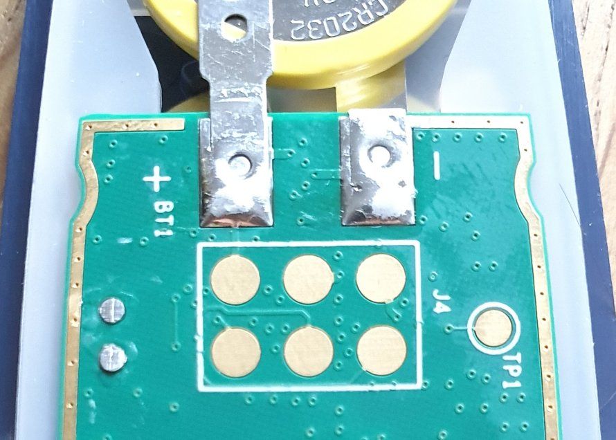
Pretty obvious it's some kind of in-circuit programming/testing/debugging port, right? Could be JTAG, but none of the common pinouts really fits. With one of the pads obviously connected to Vcc, I'd say surely another one is GND which shouldn't be hard to find, but that leaves only four signal lines. Is that even enough for a minimal JTAG? SWD would be the other popular candidate for Cortex devices, but it has only two or three lines, and all the pads seem to be connected to something.
Has anyone seen a layout like this, or any smarter idea than getting some SWD dongle and bruteforcing the remaining combinations once I've identified GND?
-
@LaoC said in Hardware debugging:
any smarter idea than getting some SWD dongle and bruteforcing the remaining combinations once I've identified GND?
Maybe f around initially with a multimeter in various safe states, starting with "off".
If power and ground are taken, a wave would indicate a clock, assuming you can probe while On without breaking it. Not sure whether to expect a clock, of course.
-
@Gribnit said in Hardware debugging:
@LaoC said in Hardware debugging:
any smarter idea than getting some SWD dongle and bruteforcing the remaining combinations once I've identified GND?
Maybe f around initially with a multimeter in various safe states, starting with "off".
If power and ground are taken, a wave would indicate a clock, assuming you can probe while On without breaking it. Not sure whether to expect a clock, of course.
As far as I understand it, everything is externally clocked so that'd be difficult. Even worse, pretty much everything has the same pullup resistors, and I think Reset and Clock are the only things that are always inputs.
-
@LaoC said in Hardware debugging:
SWD would be the other popular candidate for Cortex devices, but it has only two or three lines, and all the pads seem to be connected to something.
SWD normally uses a 10-pin connector, but 3 of those are ground, and 2 are unused, leaving 6 unique pins. So that could be SWD, although I wouldn't bet on it. If it's not SWD, I don't have a clue.